If you want to build an amplifier using a tetrode but don't want to mess around with screen and grid powersupplies
the G2DAF concept is for you!
HV and filament voltage required, just as in a grounded grid amplifier.
However, the screen (G2) voltage is derived from the input RF and the grid (G1) is at DC ground.
Check the circuit description below.
However, since a few years I have converted the amplifier to a normal tetrode amplifier with fixed voltages on G2 (900 Vdc) and G1 (-105 Vdc). This did not significantly change the performance of the amplifier, it just made it a little easier to drive. The G2DAF configuration worked flawlessly for >15 years. But as always, at some point I get the urge to change things - just because.... :-)
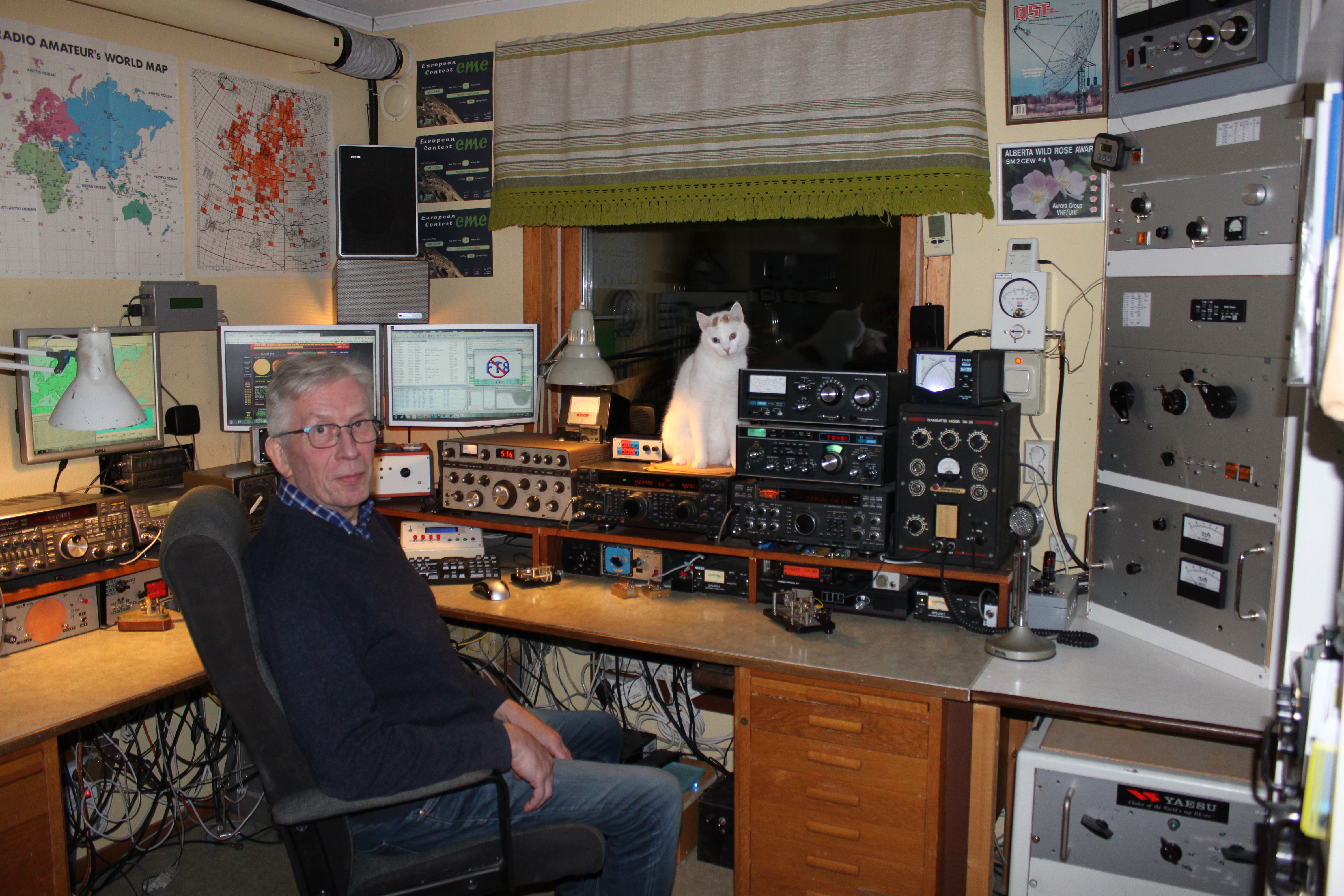
The shack, my QBL HF amplifier to the right. The bottom panel hosts the PSU for filament, screen and grid voltages for this amplifier. Above that is a 4CX350a amplifier for 144 MHz and at the top my modified LK-450 HF amplifier
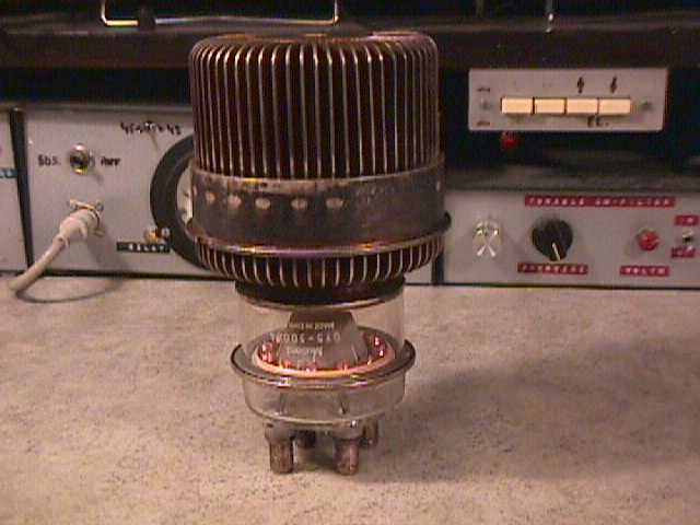
The QBL 5-3500 tube
Check some detailed pictures, circuit diagram and tube specs
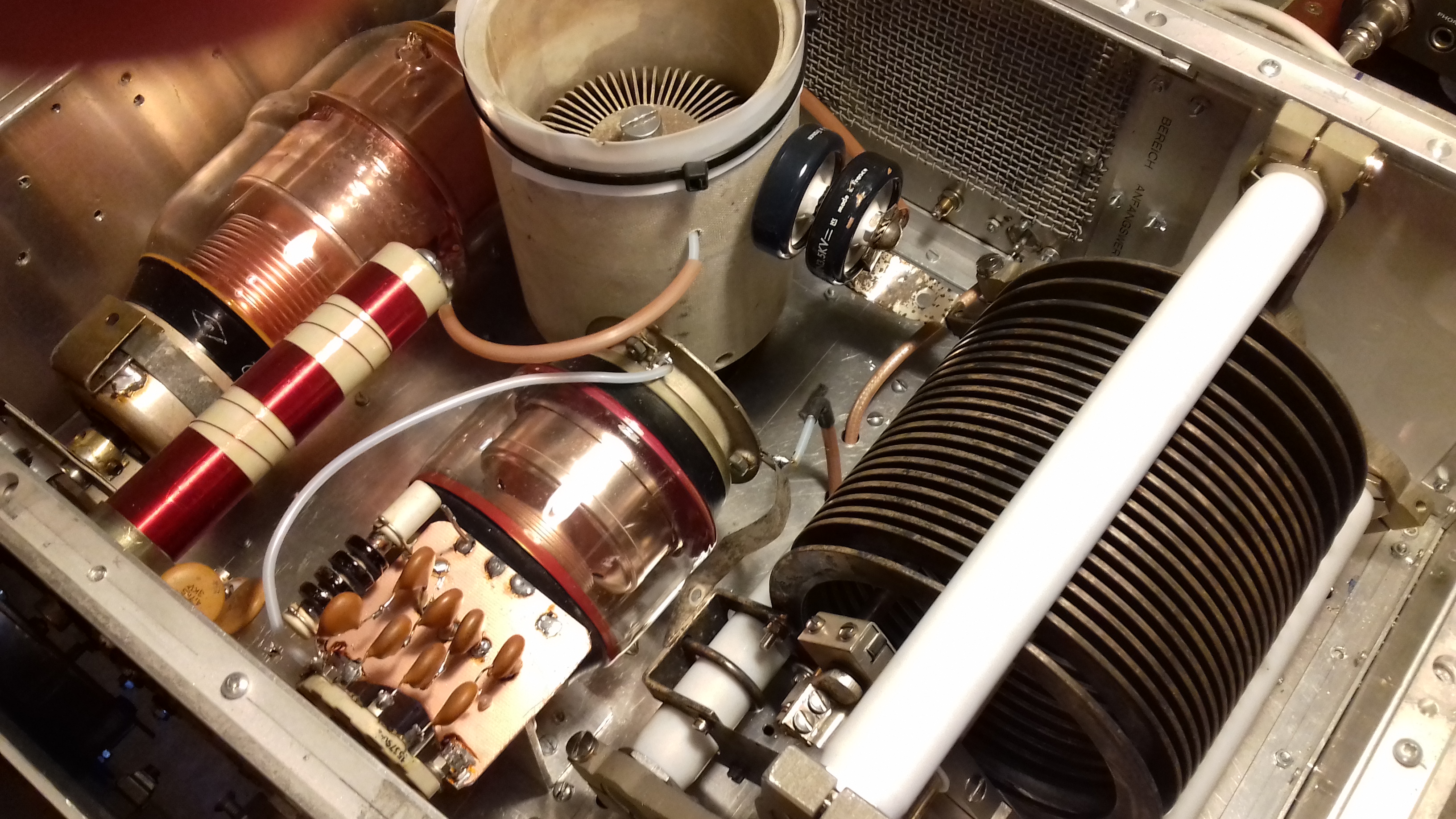
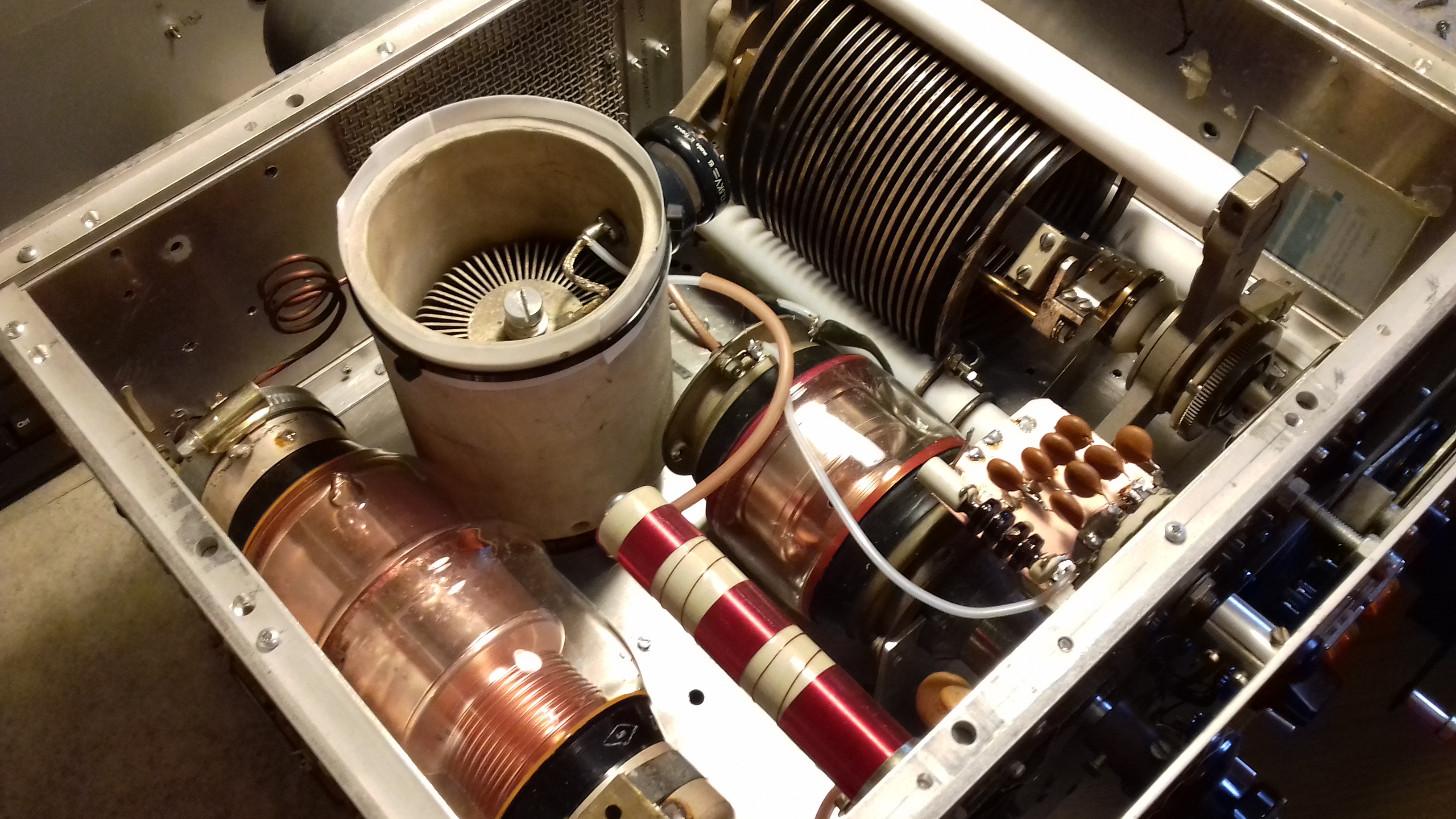
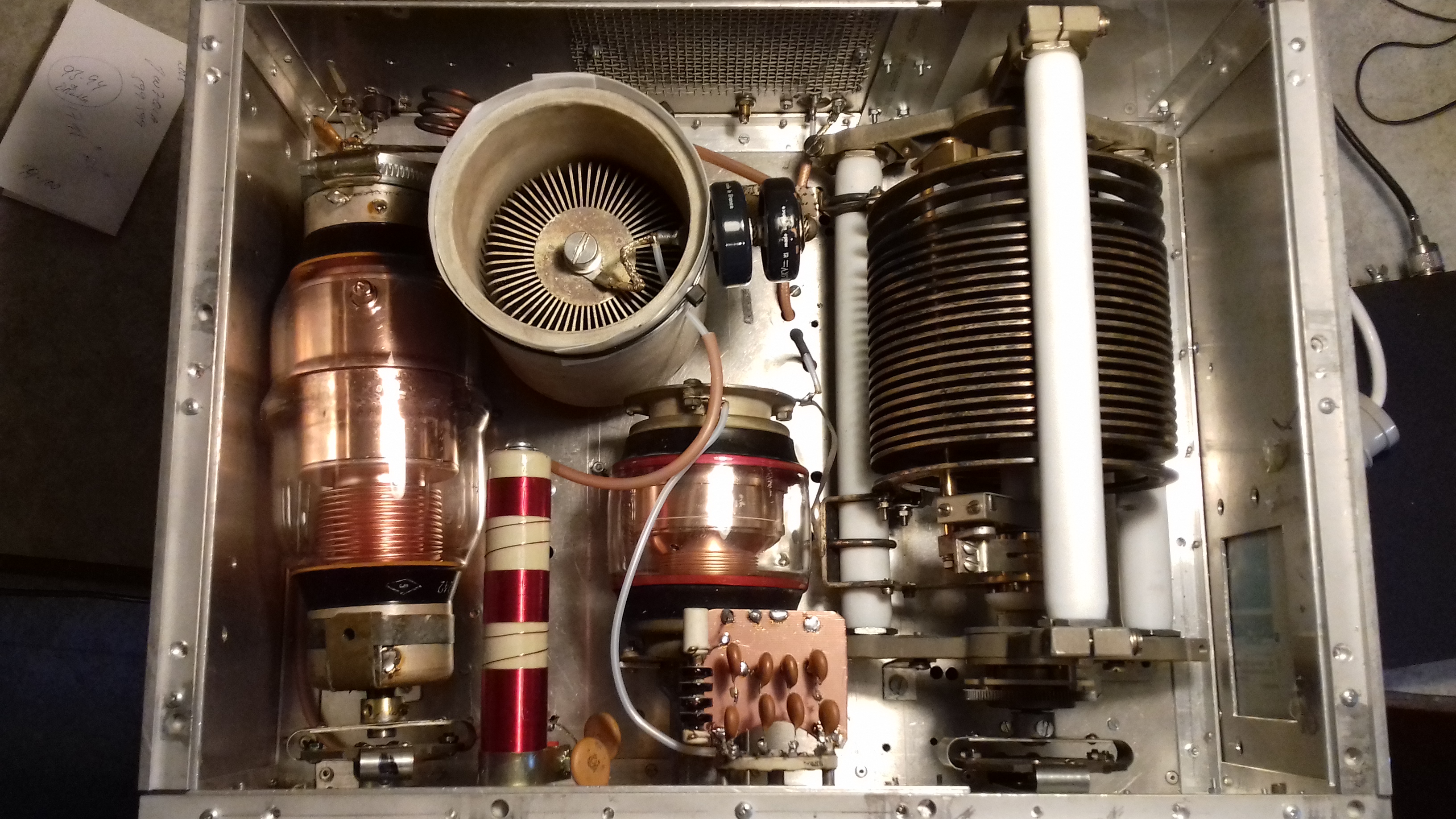
| Anode compartment | Anode plus tank circuit 160-10 mtrs |
| Anode compartment 1 | Anode plus tank circuit, side panel view |
| Anode compartment 2 | Anode plus tank circuit, top view |
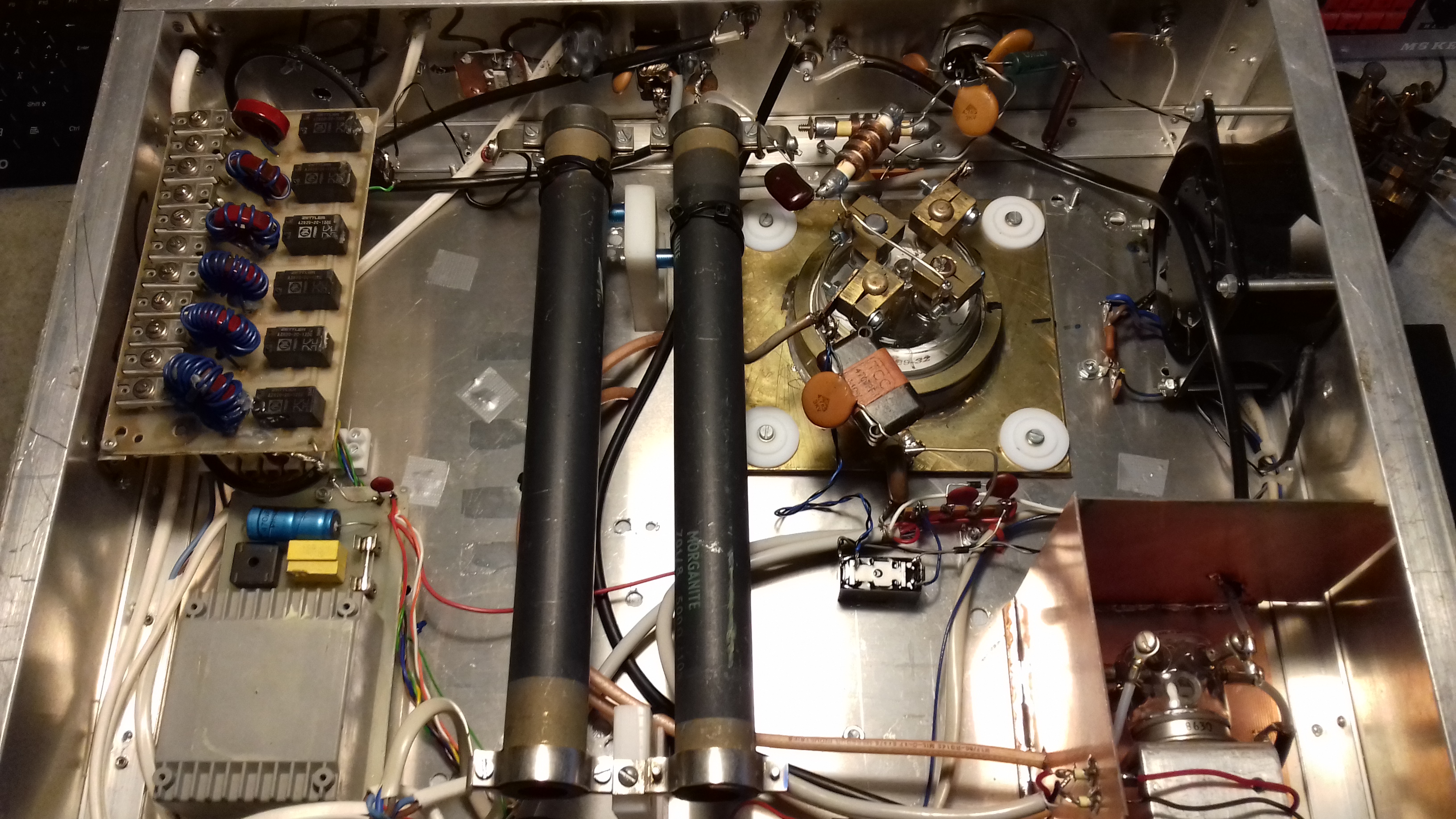
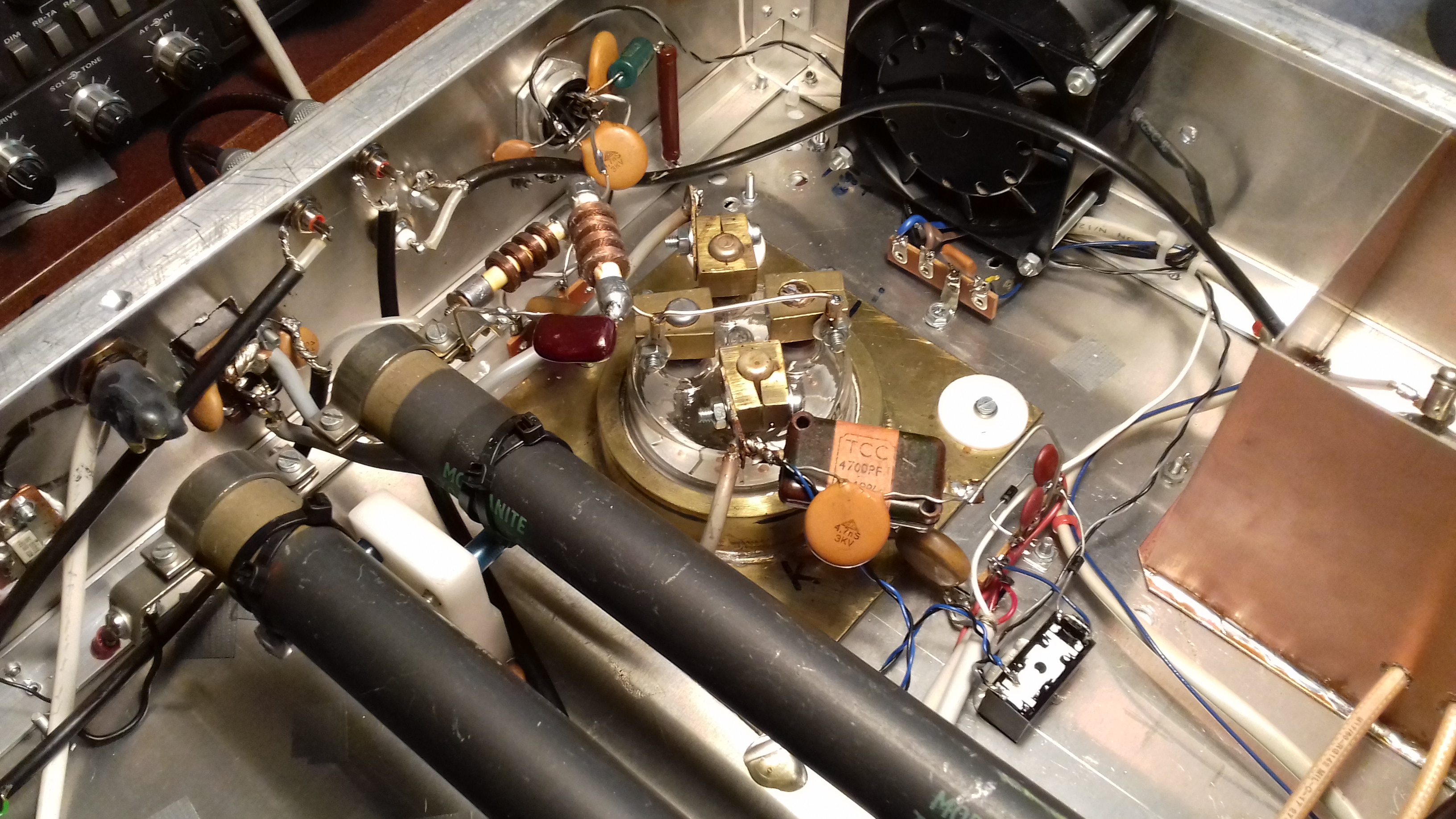
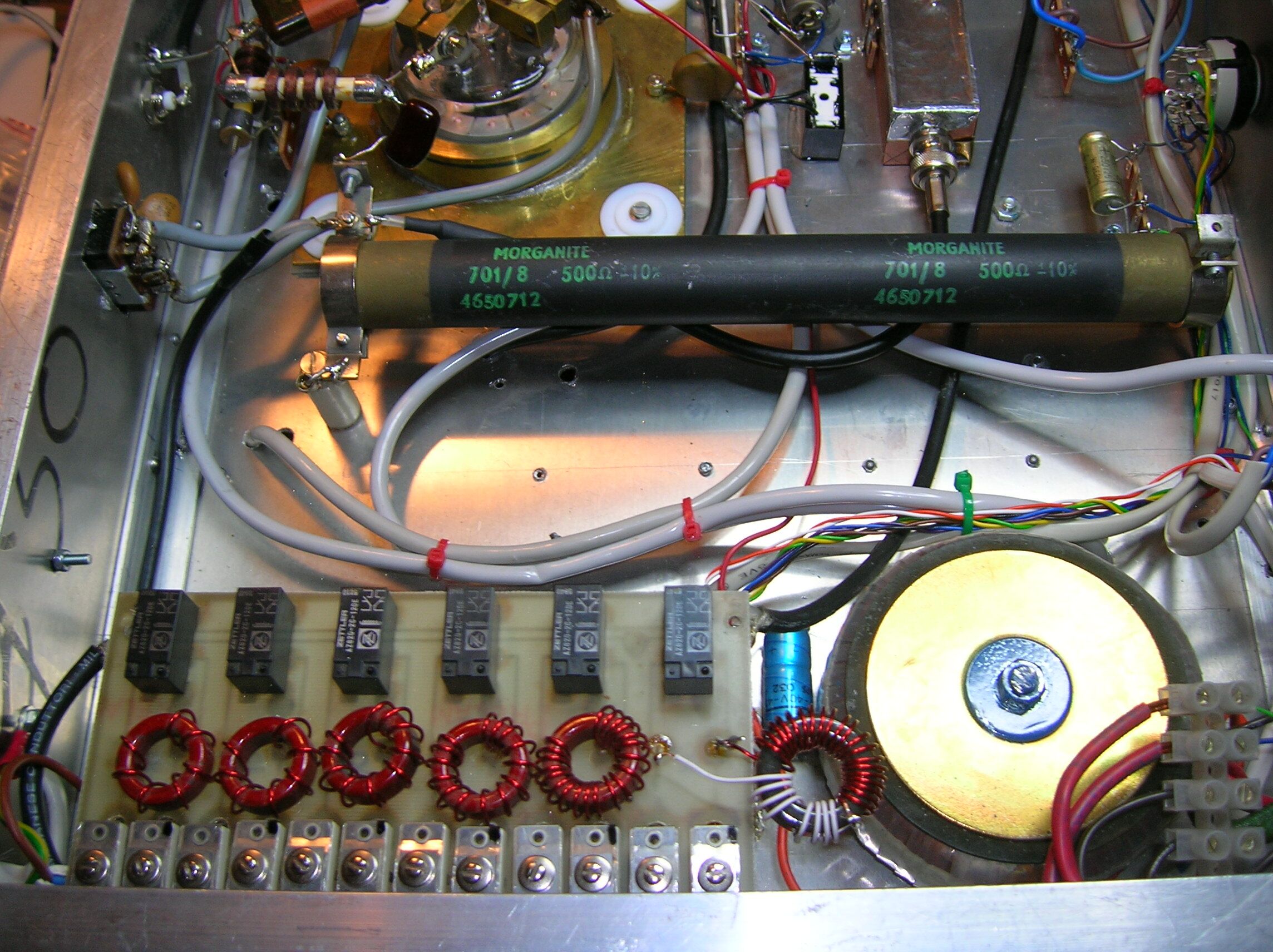
| Bottom view | Input circuit, relay pwr supply, screen bypass |
| Screen bypass 1 | Screen (g2) PTFE sandwich bypass, close view |
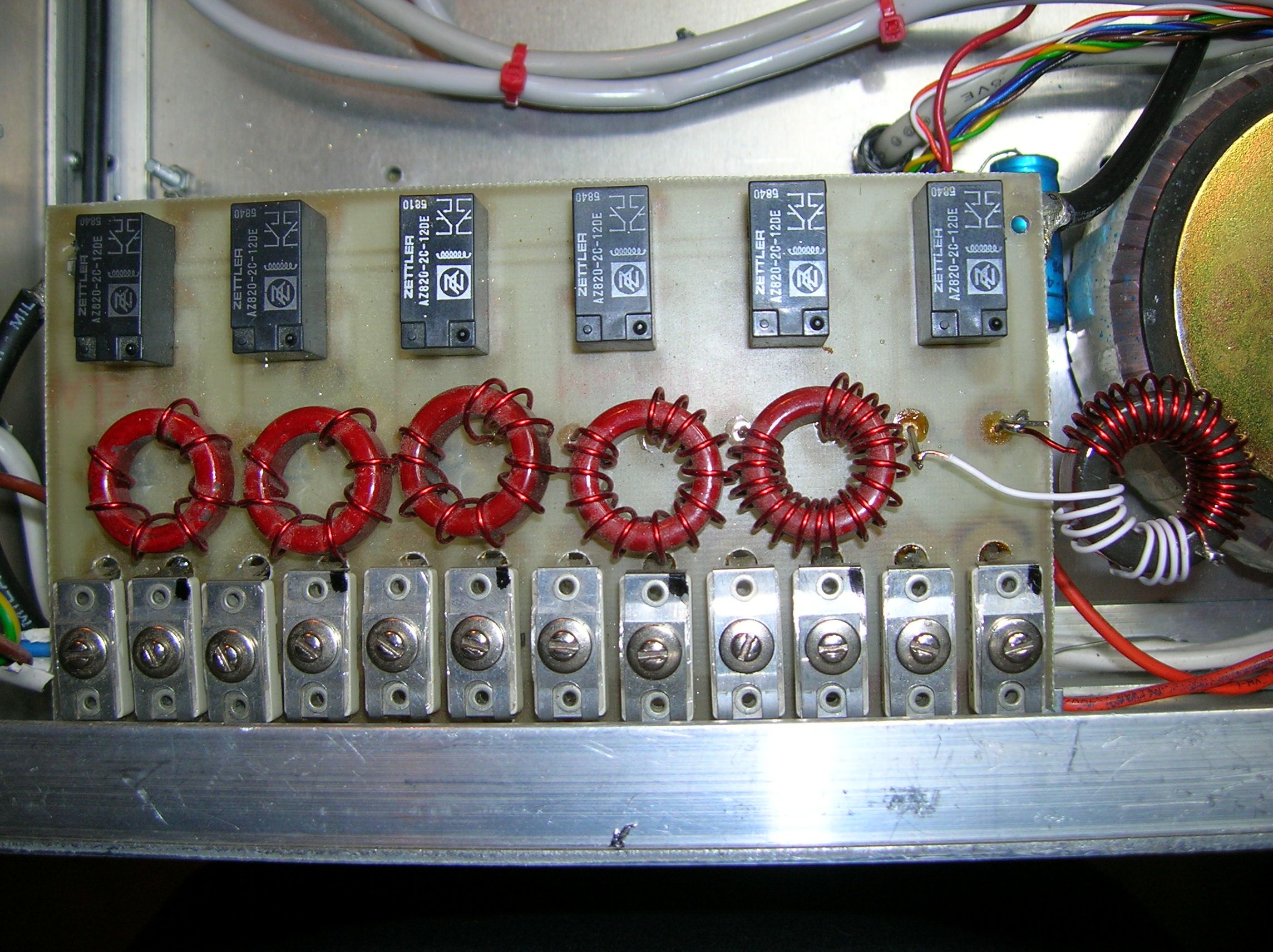
| Input | Input PI-network, relays switch different bands |
| Input 1 | Input PI-network plus input resistors |
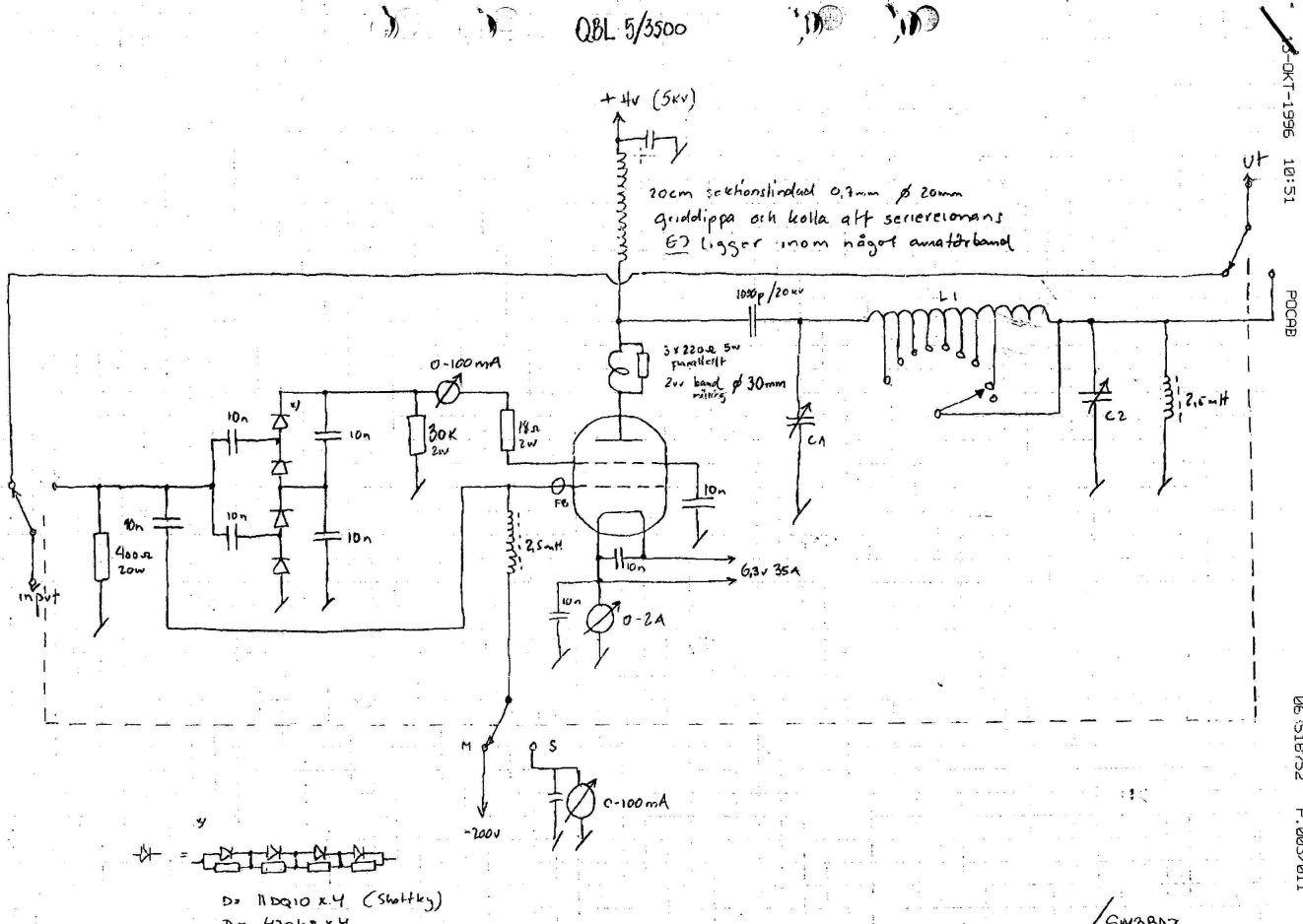
| Schematic diagram | G2DAF style QBL 5-3500 schematic diagram |
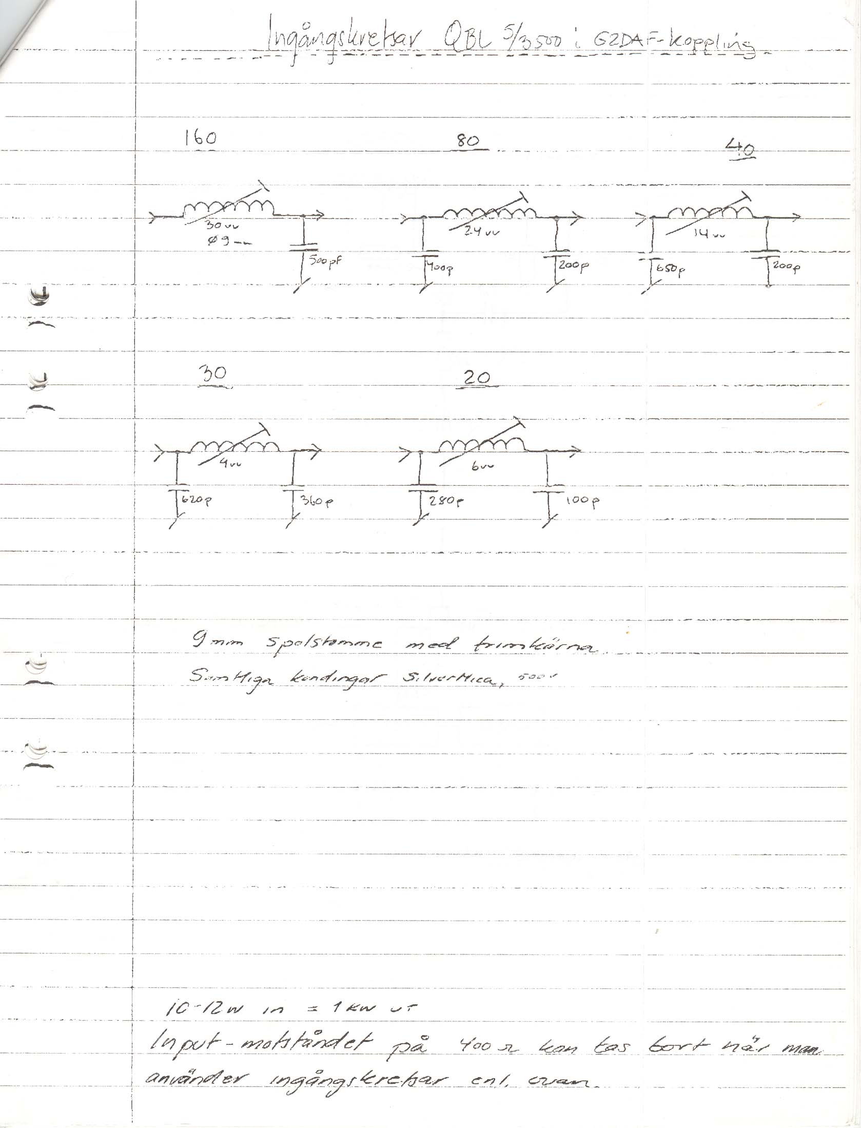
| Input circuit, coils | Schematic of input circuit using 9mm dia coils with trimmer cores |
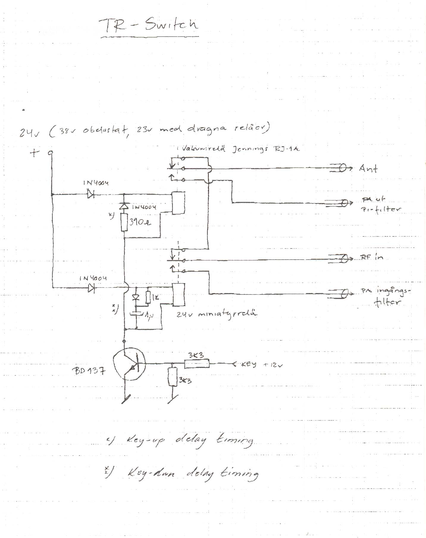
| T/R switching | T/R switching using RJ-1A relays |
| QBL 5-3500 specification sheet | PDF with all tube data. (1Mb) |